
Support: Livewire Pro I/O Expander User Guide
Document Version: 1.2
Applicable Products
This guide is applicable to the following BrickHouse Security and BrickHouse GPS products.
GPS Trackers
| Product Features | Livewire Pro |
|---|---|
| LTE Network Connectivity | Cat M1 with 2G fallback |
| Real-Time Track, Trace & Geofencing | Yes |
| Last Gasp Battery | Li-Polymer, 250 mAh |
| Internal Buzzer | No |
| Vehicle Diagnostics Protocol Supported | |
| OBD / Odometer | With CANBus Adapter |
| J1939 Heavy Duty | Yes, native |
| J1708 Heavy Duty (Legacy) | With CANBus Adapter |
Glossary
- 1-Wire: A single-wire data interface (plus ground). It connects one accessory, such as an iButton reader, temperature sensor or I/O Expander, to the Livewire Pro's green wire (#16).
- Analog Input: An input that reads a variable voltage instead of just on/off. The Livewire Pro's analog input (Brown, #7) reads 0 to 32 V DC.
- CAN High / CAN Low: The two wires that carry CANBus data. They must never be swapped.
- CANBus: Controller Area Network. The data network a vehicle's computers use to share engine and dashboard information.
- Digital Input: An input that reports one of two states, such as door open or closed. Livewire Pro inputs trigger when connected to ground.
- ELD: Electronic Logging Device. Records a commercial driver's hours of service.
- GND: Ground. The vehicle's chassis or battery negative connection. Every accessory needs one.
- IMEI: International Mobile Equipment Identity. A 15-digit number uniquely identifying a mobile device, often found on the device label.
- Ignition (ACC / RUN): The vehicle circuit that has power only when the key is on. The Livewire Pro uses it (White, #3) to detect when the vehicle is running.
- J1708: A communication protocol and 6-pin connector standard. Primarily used in pre-2005 heavy-duty vehicles for transmitting data between vehicle components.
- J1939: A higher-layer protocol and 9-pin connector standard. Supersedes J1708.
- Last Gasp Battery: The Livewire Pro's small internal backup battery. It lets the device report after vehicle power is lost.
- Locate: The BrickHouse GPS tracking platform, on the web and in the mobile app.
- LTE Cat M1: Low-power LTE cellular networks built for tracking devices. The Livewire Pro falls back to 2G where they are not available.
- OBD-II: On-Board Diagnostics, Second Generation. A standardized system and 16-pin connector used mostly in light-duty vehicles for self-diagnostics and reporting.
- Open Drain Output: An output that switches the ground side of a circuit. The device it controls gets its positive (+) power separately.
- PTO: Power Take-Off. Engine-driven equipment such as a pump, lift or winch. Often monitored with a digital input.
- Relay: An electrically controlled switch that lets a low-current output control a high-current circuit. Terminals 85 and 86 power the coil; 30 and 87 carry the switched circuit.
- RP1226: A modern heavy-duty diagnostics protocol and 14-pin connector standard. Introduced in commercial vehicles from 2019.
- RS232: A serial data connection standard. The Livewire Pro has two RS232 ports for accessories such as the CANBus Adapter and I/O Expander.
- RX / TX: Receive / Transmit. On a serial connection, TX on one device connects to RX on the other.
- Sleep Mode: A low-power state a device enters when the vehicle is off, to avoid draining the vehicle battery.
- Sync: The CANBus Adapter's process of detecting the vehicle's data format. Runs automatically on first power-up with the ignition on.
- VIN: Vehicle Identification Number. A unique serial number used to identify individual vehicles.
- Wiring Harness: The bundle of color-coded wires that connects a device or accessory to the vehicle and to other devices.
- Y-Cable: An adapter cable that splits an existing port into two, allowing multiple devices to connect to a single source.
Overview
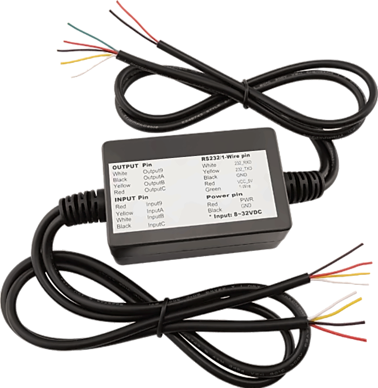
The Livewire Pro I/O Expander adds 4 digital inputs and 4 digital outputs to your Livewire Pro. Use it to monitor more sensors (doors, PTO, switches) and control more devices (relays, lights, buzzers) than the Livewire Pro's built-in wires allow.
What's in the box
- Livewire Pro I/O Expander module
- 1.2 m wiring harness
You will also need: a Livewire Pro (sold separately). To control engine shut-off or door locks, add Livewire Relays (sold separately).
How it works
The I/O Expander connects to one of the Livewire Pro's RS232 serial ports using 3 wires (transmit, receive and ground) and takes its own power from the vehicle. The Livewire Pro reads the expander's 4 inputs and switches its 4 outputs over that serial link, so input events show up in the Locate platform and outputs can be triggered by commands, rules or alerts.
- Inputs detect when a switch or sensor changes state, such as a door opening or a PTO engaging.
- Outputs are open drain: they switch a device's ground side on or off, up to 750 mA each. Use a Livewire Relay for anything that draws more, such as a starter or door lock circuit.
The expander uses one of the Livewire Pro's two RS232 ports. Alternatively, it can also connect to the Livewire Pro's 1-wire port. If you also plan to install CANBus Adapter, contact us first so we can plan which accessory goes on which port.
Specifications
| Specification | Value |
|---|---|
| Digital inputs | 4 |
| Digital outputs | 4, open drain, 750 mA max each |
| Operating voltage | 8 to 32 V DC (12 V and 24 V vehicles, no converter needed) |
| Connection to Livewire Pro | Option 1: RS232 (TX, RX, GND) Option 2: 1-wire (1-wire, GND) |
| Accessory power output | 5 V |
| Connector | 15-pin |
| Harness length | 1.2 m (3.9 ft) |
| Dimensions | 80 × 50 × 30 mm (3.15 × 1.97 × 1.18 in) |
| Compatibility | Livewire Pro |
Harness wire guide
The harness splits into 4 groups. Wire colors repeat between groups, so always identify a wire by its group first.
Output Group
| Wire color | Function | Rating |
|---|---|---|
| White | Output 9 | Open drain, 750 mA max |
| Black | Output A | Open drain, 750 mA max |
| Yellow | Output B | Open drain, 750 mA max |
| Red | Output C | Open drain, 750 mA max |
Input Group
| Wire color | Function | Rating |
|---|---|---|
| Red | Input 9 | Digital input |
| Yellow | Input A | Digital input |
| White | Input B | Digital input |
| Black | Input C | Digital input |
Power
| Wire color | Function | Rating |
|---|---|---|
| Red | Power in (+) | 8 to 32 V DC |
| Black | Ground |
Connect to Livewire Pro
You can connect to the Livewire Pro using EITHER the 1-wire (green) OR both RS232 wires (white & yellow). In both cases, 5V (red) and Ground (Serial, black) need to be connected to the Livewire Pro.
| Wire color | Function | Rating |
|---|---|---|
| White | RS232 receive (RX) | RS232 level |
| Yellow | RS232 transmit (TX) | RS232 level |
| Black | Ground (Serial) | |
| Red | 5 V output | |
| Green | 1-Wire |
Insulate and tape back any wire you do not use.
Wiring to the Livewire Pro
Connect power and ground first, then the serial wires (EITHER 1-wire OR RS232). For RS232, transmit (TX) on one device always goes to receive (RX) on the other.
RS232 Connection
| I/O Expander wire | Connects to | Livewire Pro wire (pin) |
|---|---|---|
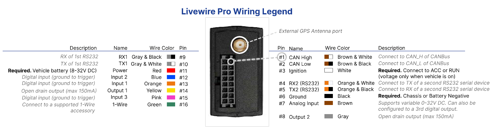
| Power: Red | Vehicle battery positive (constant 12/24 V), fused | Same circuit as Livewire Pro Power, Red (#11) |
| Power: Black | Chassis or battery negative | Same point as Livewire Pro Ground, Black (#6) |
| Serial: Yellow (TX) | Livewire Pro RS232 port 1 receive | RX1, Gray & Black (#9) |
| Serial: White (RX) | Livewire Pro RS232 port 1 transmit | TX1, Gray & White (#10) |
| Serial: Black (GND) | Livewire Pro ground | Ground, Black (#6) |
If port 1 is already in use, the expander can use RS232 port 2 instead: Yellow to RX2, Orange & White (#4), and White to TX2, Orange & Black (#5). Tell us which port you used so we configure the right one.
1-Wire Connection
| I/O Expander wire | Connects to | Livewire Pro wire (pin) |
|---|---|---|
| Power: Red | Vehicle battery positive (constant 12/24 V), fused | Same circuit as Livewire Pro Power, Red (#11) |
| Power: Black | Chassis or battery negative | Same point as Livewire Pro Ground, Black (#6) |
| 1-wire: Green | Livewire Pro 1-wire (green) | 1-wire, Green (#16) |
| Serial: Black (GND) | Livewire Pro ground | Ground, Black (#6) |
See the Livewire Pro Wiring Legend below for the full output.
Livewire Pro Wiring Legend

Wiring inputs and outputs
Inputs. Connect each sensor or switch to one input wire in the Inputs group. Each input reports two states (on/off), such as door open/closed. Inputs trigger when connected to ground, the same as the Livewire Pro's built-in inputs. Use sensors and switches that close to ground when active.
Outputs. Each output switches the ground side of the device it controls:
- Connect the device's positive (+) wire to fused vehicle power.
- Connect the device's negative (-) wire to an output wire in the Outputs group.
- When the output turns on, it completes the circuit to ground and the device runs.
Do not exceed 750 mA per output. For high-current loads, drive a Livewire Relay instead:
| Livewire Relay terminal | Connects to |
|---|---|
| 85 (coil) | An I/O Expander output wire |
| 86 (coil) | Fused vehicle power (12/24 V) |
| 30 and 87 | The circuit being switched |
Relay installations can affect vehicle safety. We recommend a professional installer for these.
Setup and configuration
Special configuration is required. The I/O Expander will not work until we enable it on your Livewire Pro. Contact us before or right after installation and we will set it up for you.
When you contact us, have ready:
- Your Livewire Pro's IMEI or device name in Locate
- Which RS232 port you wired the expander to (port 1 or port 2)
- What each input and output is connected to, and how you want it named and alerted in Locate
Installation tips and troubleshooting
- Mount the expander on a solid surface away from heat, moisture and moving parts, and secure the harness with cable ties.
- Disconnect the vehicle battery before splicing into power wires, and fuse every power connection.
- Do not install wiring where it can be pinched or rub against sharp metal.
| Problem | Check |
|---|---|
| Inputs or outputs never respond | Confirm we have enabled the expander on your device. Check that TX and RX are not swapped and that ground is connected. |
| An input shows the wrong state | Inputs trigger on ground. Check that the sensor closes to ground when active. |
| An output turns on but the device does not run | Check the device's power feed and fuse, and that its load is under 750 mA. |
| Expander has no power | Check the Red and Black power wires and the fuse. Voltage must be 8 to 32 V DC. |
Technical Support & Contact Information
For technical assistance, advanced troubleshooting, or further product information, please contact:
Expert Phone Support
Representatives available seven days a week, 9am - 9pm ET.
- Toll Free: (800) 654-7966
- International: +1 (925) 326-3688
- Online: brickhousesecurity.com/gps-trackers/livewire-pro-i-o-expander
- Help center: help.brickhousesecurity.com
Thank you for choosing BrickHouse Security.
Mar 6th 2024